During the past year or so I have been
building some electronic projects at home during my spare time.
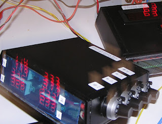
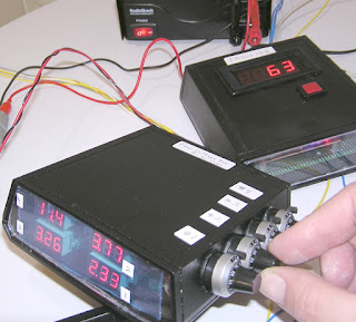
These are small hand-held test
instruments. Top right is an event counter module.
The event counter module will count
the number of events (off to on transition) during a set length of time.
Bottom left is a voltage source
module.
In a vehicle, voltages can represent
fuel level, air pressure, ride height, etcetera.
For my test bench, I needed a module
that could simulate these voltage inputs to a control system.
The voltage source module has four
resistors, four voltage displays, and four circuit protection items, i.e. 250
milli-ampere fuses.
Grab one of these ten-turn knobs and
select any voltage from zero through five volts.
Read the four voltages from the
endplate window.
Kind of like an early tricorder.
From Wagon Train. Before there was a
Star Trek.
The next project started out simple
enough.
Generic 4 - 20 milliamp current loop
input is a very low voltage which goes through a variable resistor to ground.
Connected to "Instrument
Ground" in the vehicle. Not
"Chassis Ground".
The box seemed kind of empty. Needed
some more things to fill it up.
It has three resistors and three switches, for use when things go right.
It has three of the 200 mA fuses for when things go wrong.
Why not add some milliameters?
Why not add some nifty 0 - 100 %
nameplates?
Each resistor has a switch that may
connect one end, or the other end, of the resistor to "Instrument
Ground."
Some fuel level sensors have five ohms
when empty, 90 ohms when full.
Some fuel level sensors have 90 ohms
when empty, five ohms when full.
In any given prototype vehicle, we
don't know which type of fuel level sensors we are going to get. Using this test box, we can just flip a
switch to select which end "0%" or "100%" represents
"Fuel Tank Full."
RESOLUTION
Off-the shelf behavior of the
milliamp meter would indicate zero for any amount of current less than ten
milliamperes.
We need to measure four milliamperes
and up. Therefore we choose to change the resolution of the milliamp meter.
We will change the resolution ten-to-one,
so that the ammeter will read all the
way down to one milliampere.
The original shunt wire probably had a
resistance of 0.005 ohms or so.
Replacing that with a 0.05 ohm
resistor resulted in some readings that were a little too high. A little bit
more that 10 to 1. In other words the readings were inaccurate.
Experimenting with some small value
resistors, a parallel combination of 0.49 ohms and 0.05 ohms brings about 0.049
ohms.
The results are pretty good. We add 0.39 ohm (black orange white gold) and
0.01 ohm (black brown black gold).
I did not hack in far enough to move
the decimal point on the display.
0.39 ohms and 0.1 ohms makes 0.49 ohms approximately.
0.49 ohms in parallel with 0.05 ohms results in 0.49 ohms approximately.
Reading is 0.5 milliamps low. Good enough for bench work.
[Projects_3F.JPG]
[Projects_3H.JPG]
[Projects_3I.JPG]
fin


